Wind/Solar
Hookup Basics and Beyond.
Click on an item above for more specific information
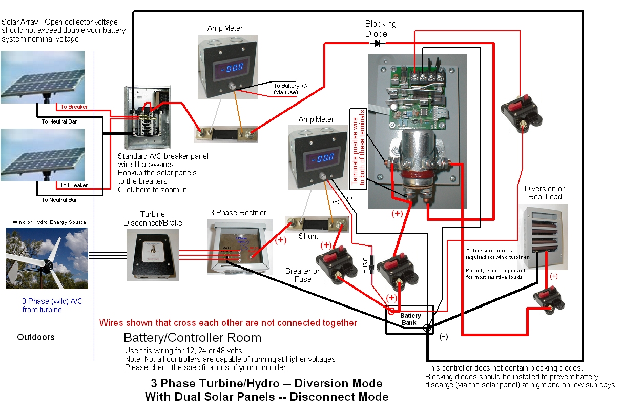
The image above shows the recommended wiring diagram for a 3 phase wind turbine or water hydro.
Along with multiple solar panels wired in parallel, terminated via a standard A/C sub panel.
Here is a very similar diagram as found on page 6; however, we are adding multiple solar panels and discussing the use of power distribution panels.
The controller depicted is the Coleman Air C440-HVM. This is a high capacity, solenoid based, single stage controller, well suited for wind and suitable for solar if you are on a budget. The C150-SMA controller is recommended instead of the C440-HVM for medium to larger solar systems. Please check the specification of your controller before installing it to insure it is recommended for the voltage of your battery bank. Although we have shown the C440-HVM running both wind and solar at the same time, we prefer to use PWM controllers for solar when possible. Often the best choice is to use the C440 line for the wind, with a separate C150-SMA or C60 (both are PWM controllers), for the solar. PWM controllers offer better battery longevity.
The turbine is mounted on a pole, preferably 30' or higher above the tallest object that is within 100 feet (300' is preferred) from the turbine. The three wires are normally routed through the inside of the pole. Most turbines do not require slip rings as the turbine will go one direction about as much as it goes the other. Often a #12 gauge outdoor extension cord is used from the turbine to the ground, as these cords are quite flexible and durable.
Be sure to ground your turbine and pole using a copper ground rod hammered deep into moist earth. Failure to properly ground your turbine WILL almost certainly result in equipment loss due to lighting and static discharges.
The 3 phase wiring can be smaller than the D/C wiring as each wire only carries 66% of the total current being generated by the turbine. On the D/C side, each wire (two wires) carries 100% of the total current (What comes in, must go out.) See our wire size calculator for more information about wire size.
Inside the battery/controller room, the turbine is connected to a 3 phase disconnect/brake. This allows the turbine to be disconnected from the rectifier/battery by simply flipping a switch. In the full down position, the 3 phases (wires) of the turbine are shorted together, causing a large load to be placed on the turbine, significantly restricting it from spinning in most winds. In very high winds, the turbine may overcome this short circuit load and spin (perhaps quite fast), even with a full brake applied. It is not recommended to apply the short circuit brake during a high wind event unless the brake can be applied during a low. The best way to know when the winds are a bit lower is to incorporate a amp meter in your system (as shown.) The brake should always be applied before you service the turbine. In addition, tying or otherwise restricting blade movement during turbine installation/service is essential to safety. A spinning turbine blade can slice though a skull like a knife though butter -- be safe!!
Leaving the turbine/disconnect switch, the 3 wires are routed and terminated to the 3 phase input of a suitable 3 phase rectifier. The 3 phase rectifier depicted above is the Coleman Air - R150 rectifier, your system may not require such a large rectifier. Smaller rectifiers are readily available as well. The 3 phase rectifier, rectifies (converts) the pulsing A/C (alternating current) into D/C (direct current). The D/C output voltage (of the rectifier) will be 1.3 times higher than the RMS A/C that is entering the rectifier. For example, if you measure the incoming A/C voltage on any two A/C wires, and your meter reads 18 volts A/C, then you can expect to see about 23.4 volts D/C leaving the rectifier (on the D/C terminals). A rectifier does not downshift or up-shift the voltage. The 1.3 times is simply because you have three current carrying wires coming in, verses two leaving. There are other factors including the conversion from RMS (root mean square), but to keep it simple, 1.3 times any incoming pair will equal the D/C out.
Leaving the rectifier, the D/C current is routed though a shunt resistor for the matching amp meter. A shunt resistor causes a very SMALL voltage drop which is directly proportional to the current flowing though it. This small voltage drop is measured by the amp meter. Thus the amp meter displays the current flowing through the shunt (which of course is the current from the turbine to the battery bank). Analog amp meters are are also a valid choice and can be more economical. Dual voltage/amperage meters can be used as well if your controller does not have a voltage meter. An amp meter is not required but not having one really puts you in the dark when it comes to knowing how your turbine is performing. Also, as mentioned above, applying a brake in very high winds can actually destroy the turbine, so an amp meter can be used to know when to apply a brake.
About Breakers: Leaving the shunt, we route our positive wire to a breaker or fuse. The purpose of this fuse is not really to protect the battery (or anything else) from the turbine, but to protect everything (including the battery) from the battery. Batteries are capable of supplying massive amounts of current (in excess of 900 amps!) that can weld metal, start fires and given the right conditions, electrocute people. Basically, anytime you run a wire from the positive post of the battery it should go though a breaker or fuse. The fuse should be rated higher than the anticipated current that the leg will handle. If your turbine is capable of producing 50 amps in the best of conditions, then you might consider an 80 amp breaker or fuse. This ensures that the breaker will never trip due to normal currents from the turbine, but only trip if something really wrong has occurred (like you accidentally touch the positive wire to a ground.) -- If you are installing your system based on local/state codes, you almost certainly will be required to have breakers and disconnects in your system. Not having them is REALLY REALLY DANGEROUS!
Many installation codes require a breaker to be accessible without having to open up an enclosure where the operator can contact any current carrying wires or busses. A small breaker box (sold at the hardware store) can be a really handy item when you have multiple wires leaving your battery bank (See below for more information.) Wiring your battery to the top of the breaker box, you then run your turbine to a breaker, your controller to a breaker, your inverter to a breaker, etc. Please note there are differences in D/C current Vs A/C current when it comes to breakers. The use of an A/C breaker box may not pass mustard with your inspector. You can Google this subject for more information.
The breakers depicted above have both automatic and manual disconnects along with manual resets. This allows the breaker to be used as a switch, in addition to providing over-current protection. Please check your code restrictions on using a breaker as a switch.
Leaving the breaker, we finally arrive at the battery, where the turbine's energy charges the battery (as long as the turbine's voltage is higher than the battery voltage of course.)
See our FAQ's about turbine voltages and currents.
The Controller:The basic operating philosophy of a diversion controller is quite simple. Monitor the battery voltage, and if it should rise to a predetermined level, connect a diversion load or "Dummy Load", of sufficient size, to the battery or energy source to prevent the battery voltage from increasing any further. This is a very simple, yet very effective way of preventing battery overcharging. See the discussion on controllers for more information.
The Diversion Load: The Diversion load or real world load is routed to the controller via a breaker or fuse. Again, this fuse should be sized larger than the amperage you expect the diversion load (or working load) will draw on a normal basis. If you have a 60 amp load, then a 80 amp breaker should be fine. Be sure your wires are large enough to handle the amperages that may be allowed to pass via the breaker. (The wire must be larger than the breaker.)
Diversion controllers work by diverting excess energy from the wind turbine to a diversion or "dummy load". This diversion allows the turbine to remain under a load at all times. A solar panel may be safely disconnected from the batteries, but an active wind turbine should never be disconnected from its load (battery/diversion load). When a wind turbine is not loaded, it can easily speed out of control in high wind events, which can lead to catastrophic failure of the turbine as well as the possibility of damage and injury to other property and people. It is very important that your turbine has a very reliable load at all times. Please see the full discussion on diversion loads.
Three phase wind turbines are by far the most popular stator (the inside of the motor/alternator) design used by the larger turbine manufactures, and increasingly by the smaller turbine vendors. They can be very efficient, can be very long lasting (no brushes), can offer very good current handling both in and outside of the stator due to the 3 wires Vs 2 wires.) Given a choice between a three phase system and a single phase A/C or D/C system, the 3 phase system should hold the advantage, all other things being equal of course.
For this discussion, let's assume we have a 24 volt battery bank. Based on this, we have shown two banks (of two panels each), wired in parallel. Each panel in each bank is 1st wired in parallel together, usually via a MC-4 "Y" connector. When you wire panels in parallel, the voltage remains the same, but the amperage is summed. In this configuration, the two "24" volt panels of 8 amps each (192 watts), turns in to a single output of 24 volts, at 16 amps. (384 watts.) Should we own 12 volt panels instead, and want to use them in our 24 volt battery bank, then we would wire two panels in series, the two panels would then be joined in parallel with the other banks. When you wire in series, you sum the voltage, but the amperage stays the same. For instance, two 12 volt, 8 amp panels wired in series, yields a single output of 24 volts at 8 amps. Note: We refer to panels as 12 or 24 volt panels, yet the voltage output of a solar panel must always be higher than the nominal battery voltage, generally by 1.5 times. A 12 volt panel will probably have a open circuit voltage (VOC) of least 18 volts. -- More on this can be found by clicking here.
Each of the banks is then routed into a breaker (20 amps is fine for our 16 amp solar banks) within the solar panel distribution box.
Standard A/C breaker box used as a solar distribution panel.
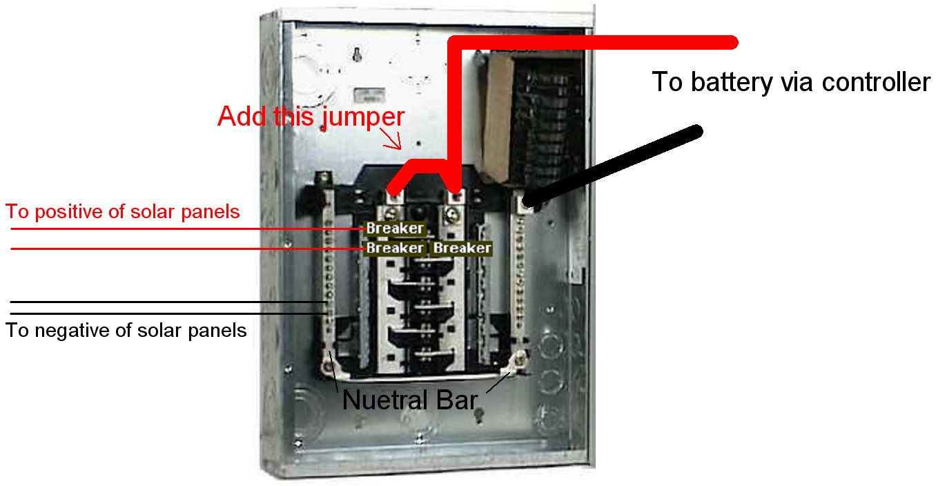
The breaker box above is a standard A/C breaker box purchased at Home Depot or Lowes etc. This GE box comes with several breakers (shown in the upper right.) By tying the two main lugs (top lugs) together, we turn the two phase box into a single phase box. (We don't need two outgoing positive wires, just one.). The beauty of this box is the price and availability, and it comes with breakers. Really a great little budget saver. Please check your code requirements, as this box wired backwards may not be allowed in all locations.
By using individual breakers for each panel (or bank of panels), we can isolate problems very easily. Should you suspect your panels are not performing properly, by simply clicking a few breakers, you can do some comparisons between panels (or panel banks). This also leads to a very quick and clean method of paralleling panels without having to purchase a many "Y" MC-4 connectors.
Note, we are actually back feeding the distribution panel, the solar energy comes into the breaker (instead of leaving it), but the breaker does not care, it is not polarity sensitive. There may be some differences in total current allowed through the breaker for the D/C verses A/C current, however, we have noticed it to be of any significance.
A panel like this can also be used as battery distribution panel. Instead of using individual breakers or fuses for each item hooked up to your batteries, you could use a panel like this (wired in the normal forward fashion.) Once again, this allows for a very neat, easily wired solution, possibly replacing a dozen or more wires and external breakers hooked up to your battery terminals.
Be sure to use breakers rated a little higher than your solar panel (or bank of panels), or you will be tripping breakers during normal conditions. If you have wired four, 8 amp panels together via "Y" connectors (MC-4 parallel), and you bring this bank into a single 20 amp breaker, you're going to be tripping the breaker as soon as the sun gets a good look at the panels. A 40 amp breaker would be a better choice.
From the breaker panel, we proceed though the shunt of the amp meter and then though a blocking diode. If you are using one of our PWM controllers, you will not need a blocking diode (the controller itself prevents back feed). The job of the blocking diode is to prevent back feed at night and very low sun days. Since the C440-HVM allows energy to flow either way though the solenoid, a blocking diode is used to prevent reverse current flow at night. We could also use multiple smaller blocking diodes on the wires leaving the solar panels. This is often preferred, since smaller more efficient diodes can be used.
After leaving the shunt (and diode), we finally get to the charge controller. The charge controller works as a simple switch to prevent the solar energy from reaching the battery once the battery gets "full". For the more technically abreast, we are using the normally closed contacts of the solenoid for the solar, and the normally open contacts for the diversion load. Basically, when the batteries get full, the solar is disconnected, and the diversion load is connected. This shuts off the solar, and engages the load at the same time. For a more advance charging algorithm, a PWM controller is preferred for the solar side of the equation.
The positive and negative terminals of the PCB on the controller are wired using independent wires and an independent breaker. This is to insure the controller is always properly connected to the battery. This is very important to prevent damage to the controller. Also be sure you disconnect the wind and solar panels before you disconnect the controller. Always, turn on the controller 1st, then the turbine/solar panels. By doing this, the controller is always properly referenced to the battery, this prevents wild voltage swings at the controllers input.
That's pretty much it. Your inverter (if you have one), will hookup to your batteries (via a breaker or fuse of course). The charge controller does not control the inverter, and the inverter does not control the charge controller. The size of the charge controller is not conditioned upon the size of the inverter and visa-versa. They are independent in the sense they both do their own thing. The controller's job is to prevent battery overcharge, and maintain a proper battery voltage to extend the life of the batteries. The inverters job is to convert the stored D/C energy into A/C energy that can be used to power household items or if you elect to purchase a grid-tied inverter, slow your meter down (or run it backwards). But that is a topic for another day.
Enjoy your projects, stay safe!! Turbines can turn into growling monsters, take the time to do it right!
Click here for diagram using the Coleman Air C60M/C1060 controller with a 3 phase turbine. (Page 6.5)
Click here for diagram using the Coleman Air C150 controller with a 3 phase turbine. (Page 6)
But I have a single phase (or D/C) Turbine -- Click here. (Page 6.75)
See our FAQ's for lots of great information.
Available manuals for each product we sell can be downloaded from the product's detail page.
![]()
![]()