 |
|
Do I need a diode for my wind turbine?
- If the turbine has brushes then yes, you need a diode.
- If it is d/c motor, then yes you need a diode.
- If it is single phase A/C you need a single phase bridge rectifier.
- If it is 3 phase A/C then you need a 3 phase bridge rectifier (like a car alternator), if it is not already included.
- Check with your turbine supplier for more info.
Click here for a 3 phase wind turbine hookup/wiring diagram
Do I need a diode for use with my solar panel?
PV panels require a diode to prevent current flow back into the battery when there is little or no light. This is called a blocking diode. We sell 3A and 8A diodes for this purpose. You might also want to install a bypass diode to prevent a shaded panel from drawing down other panels. These same diodes can be used. Place diodes in the PV J-Box. If you are using a solid state controller, you may not need a blocking diode. Our C150-SMA does not require a blocking diode.
Does a diode come with your charge controller?
No, diodes are specific to your application and the size and placement of the diodes depends on your site and energy sources in use. Different turbines require different types of diodes/rectifiers (and some do not require any). PV panels require yet a different type of diode. Please see the other Q&As here for more information on diodes.
Where do I put the diode for my solar panels?
For solar panels, we recommend you put one blocking diode on each PV panel, inside the J-BOX. The diode needs to have a voltage and amperage rating above that of the panel.
Ex: If you have two 175 watt panels each at 42 volts. You will need (two) 8 Amp, 45 volt diodes. (175 watts / 42 volts) = 4.16 amps.
+ (plus) side of the diode goes to the PV panels + (plus) terminal
Where do I put the diode or rectifier for my wind turbine?
Blocking diodes and rectifiers go between your turbine and the battery bank. If you have a disconnect switch between your turbine and battery bank, then you can put your diode/rectifier on either side of this switch. Keep in mind if you have a 3 phase turbine, you need a 3 phase switch if you place the rectifier on the battery side of the switch.
Which side is the plus side of a diode?
Smaller diodes have a silver, gray, black or white band on the cathode (negative side.) The positive side is generally unmarked.
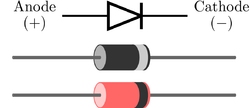
Larger stud diodes will show the arrow and line -->|--
For the symbol above: The negative side is on the right. Think of it as the current can go with the arrow, but not the other way since it hits a wall.
--> Yes,
--| No
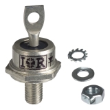 Look closely at the the diode on the left and you will see the symbol
on the right side. This shows the current goes though the diode from the
top to the bottom. For this particular stud diode, the top portion is
the anode (positive) and the bottom is the cathode (1/4" threaded
portion.) Stud diodes are also available with with the cathode on top
(Although we do not currently sell them.)
Look closely at the the diode on the left and you will see the symbol
on the right side. This shows the current goes though the diode from the
top to the bottom. For this particular stud diode, the top portion is
the anode (positive) and the bottom is the cathode (1/4" threaded
portion.) Stud diodes are also available with with the cathode on top
(Although we do not currently sell them.)
What direction does my diode go?
The positive (anode) side of the diode always goes towards your energy source, this is where your energy is coming from.
So for a solar PV panel, wind turbine, hydro etc., the anode goes on (or towards) the energy sources positive lead. No diode is required on the negative lead.
What size diode do I need?
Your diode needs to be somewhat larger than the current that is will be handling. For solar panels, we sell the 3A and 8A diodes for this purpose. If your solar panel will not exceed 2 1/2 of amps of current, then the 3 amp version is fine. The 8 amp diode is acceptable for panels up to about 7 1/2 amps. Solar panels with more charge current then this would require a larger diode such as our 85 amp diode. This larger diode can be placed in-line with the common positive wire coming from your solar panels to your charge controller to handle multiple panels at one time. Please note: This larger diode may require a heat sink if they will be used for higher power applications (above 15 amps or so.) Click here for more info.
Do your controllers handle both wind and solar?
Yes, all of our controllers work for both wind and solar Our relay/solenoid based controllers handle both at the same time, these controllers are primarily designed for turbines, but they also work for solar panels. Our solid stage controllers are perfectly suited to solar applications, yet are also quite capable as diversion controllers, these PWM controllers handle both (wind and solar) at the same time if the controller is used in the diversion mode. Please see the manuals available on the item details page for wiring details.
Do you include a diversion load with your controller?
The Coleman Air controllers do not include any type of diversion load as these loads are very specific to your particular needs. Including a diversion load would cause the product to be very limited in scope and also increase the price. Controllers that include a diversion load often burn out quickly as quality cuts are made to the load itself.
Do I need a diversion load with my solar panels?
No, if you will be using our charge controllers with solar (PV) only you do not need a diversion load. If you will be using the controller with wind only (or also), you will need a diversion load.
Do I need a diversion load for my wind turbine?
Yes, Diversion controllers work by diverting excess energy from the wind turbine to a diversion or dummy load. This diversion allows the turbine to remain under a load at all times. A solar panel may be safely disconnected from the batteries, but an active wind turbine should never be disconnected from it's load (battery/diversion load). When a wind turbine is not loaded, it can easily speed out of control in high wind events, which can lead to catastrophic failure of the turbine as well as the possibility of damage and injury to other property and people. It is very important that your turbine has a very reliable load at all times.
Can I use a grid tie inverter as a diversion load?
Yes and No. This question is asked of us nearly every day as it seems like the perfect load, but..
The most common reason you need to divert the energy from your turbine is during high wind events (like thunderstorms) -- This is also the time the grid is most likely to fail. If the grid is down, so is your load, and the turbine spins out of control!
If you have a 2nd, very reliable load, then a small (no more than 600 watts total) grid tie inverter can be used as the primary load. You will need two controllers, one for the grid tie, the 2nd for the fail safe load.
Where does my inverter hookup to your controller?
Generally inverters do not hookup to charge controllers they hookup to the battery via a breaker or disconnect. The controllers job is to prevent battery overcharge. The inverters job is to convert D/C to A/C to run A/C appliances or send power back into the grid. The size of the controller does not affect the inverter and visa/versa -- they are independent.
If however, the inverter is to be used as a "Diversion Load" as discussed in the prior FAQ (and you understand the downside to doing this), then wire the micro grid-tied inverter (no more than 600 watts total) in place of the "Diversion Load". In this case the inverter is the load for the controller. Please refer to the manual for your specific controller's for wiring details.
Please see the "Big Picture" for more information on hooking it all up.
Can I use my domestic hot water heater as a load?
Yes, but it really is not recommended unless you have two controllers. When a turbine is producing enough energy that it has fully charged the batteries and needs a diversion load, then that load must be there 100% of the time. Domestic hot water heaters cannot perform this task since once the water is hot, the heating element will be disconnected.
Can I use two controllers together?
Yes, Two controllers can be used in a fail safe system to insure there is always a diversion load available. Simply set one controllers set point lower than the other. Use the lower set point for the unpredictable/part time load (like a hot water heater) and the higher set point controller for the 100% available load (a resistor bank)
Can I use a water pump or light bulb as a diversion load? Yes, but if the pump or light fails, so may your turbine. Heating elements and resistors are by far better choices for diversion loads.
How big does my diversion load have to be? Your diversion load should be 10 to 20 percent larger than your wind/hydro energy sources. You do not need to take into account any PV panels used as they are not routed through the diversion load. Please see the controller manuals for more information.
I have a 500 watt resistor, will this work? This is a big question. A resistor rated at 500 watts means it can handle 500 watts of electricity without damage to itself, but this does not mean it will use 500 watts in all systems (at all voltages.) The actual amount of power used by a resistor depends on Ohms law (E=I/R), where E = volts, I = Amps and R = resistance in Ohms. So to determine the amps used by a resistor we will divide the volts by the ohms.
Example: A 2 ohm resistor used in a 12 volt system (set to 14.5v), will yield 7.25A (14.5/2) or 105 watts (Volts x Amps), even if it says it's a 500 watt resistor. It would require a higher voltage (just under 32 volts) to bring this power dissipation up to 500 watts for a 2 ohm resistor! For a 12 volt system, you would need a 500 watt, 4/10 (.4) ohm resistor (good luck finding that dude), or five 100 watt, 2 ohm resistors in parallel to dissipate 500 watts.
With a solar system with batteries charged, diversion is not required, but what happens to the collected energy from the panels? where does it go?
On a solar system, the controller works as a disconnect controller and simply disconnects the panels until the battery voltage lowers about .5 to .7 volts (on a 12 volt relay based system). Once the batteries reach this lower calculated point, the panels are again connected to the batteries (relays are disengaged), and the cycle continues. There is a programmatic delay to prevent quick relay cycling, yet the relays will engage and disengage as required to keep the batteries at a safe level. Note: Our solid state controllers may turn on and off several times a second.
I am thinking of using your controller with the Dummy Load being a second battery bank, what do you think?
A second battery bank is really not a good diversion load for two primary reasons.
- Hooking up a non-charged battery bank to a charged battery bank causes stress on both battery banks and especially the charged batteries. Also, if the 2nd battery bank is not in good condition, it simply wastes energy while stressing the good batteries.
- Once the 2nd battery bank is full (if it's a decent bank), then you don't have a load at all.
Can I hookup two turbines to one controller?
Yes, You can hookup as many as you like as long as the total energy from all turbines does not exceed the rating of the controller. Remember, the turbines hookup to the battery bank. The controller hooks up to battery bank and diversion load, so the controller does not care how many turbines (or PV Panels) are in the system.
Your diagram shows the turbine being hooked up directly to the battery. How can this work?
Wind turbines require a load on them at all times, so they need to be hooked up to either a battery or a matched load of some sort at all times. Once the battery is "full", then the controller "siphons" off the excess energy and sends it to a diversion load. This prevents battery overcharge. You may need a blocking diode/rectifier for your turbine (between the turbine and the battery), depending on the type of turbine you have. Please see the FAQ above for more specifics.
Why do some controllers show diagrams for hooking up the turbine to the controller, not the batteries.
Some diversion controllers have input terminals for the turbine. This is often misleading. These input terminals don't actually route any power through the electronics of the controller, they simply route the power directly from the turbine to the battery UNTIL the battery gets to a full state. At that point, the input power is diverted to the dummy load. So in essence, the turbine is hooked up directly to the batteries. The controller simply provides a termination point for the turbine. Some controllers like the Coleman Air C440-HVA do add additional functionality within the controller for the turbine, such as circuit overload protection, but even in this example, the turbine is still hooked up directly to the batteries through a breaker and shunt (for measuring amperage).
Since a turbine should see a load at all times, it is often better just to route the turbine to the batteries, then let the controller monitor the batteries and pull off any excess power as required to prevent battery overcharge.
What is the voltage input range of the Coleman Air controllers?
On the 12 and 24 volt models, the input range for the electronics is 10.5 volts to 35 volts continuous, 40 volts intermittently The input range on the relays should not exceed 40 volts.
On our 440 XL - the input range on the electronics is is 10.5 volts to 35 volts continuous, 40 volts intermittently . The solenoid can work with voltages up to 120 volts D/C or A/C
On our 440 HV series the the input range on the electronics is is 10.5 volts to 75 volts continuous, 100 volts intermittently . The solenoid can work with voltages up to 120 volts D/C or A/C
Our solid state controllers can handle larger voltages, please see the manuals for specifics.
I have a very small system at this time, will your controllers work with such a small amount of charge current?
There is no minimum size solar or wind turbine required for our controllers to function properly. Any of our controllers, even the larger ones will work with the smallest of systems.
My wind turbine puts out much more than 15 volts (for my 12 volt system), sometimes above 75 volts when the wind speed increases. Will your controller handle this?
All turbines put out more voltage (and current) when the wind speed increases. This is absolutely expected. But this voltage rise is reduced significantly when your turbine is hooked up to the battery bank. The battery bank "Clamps" the voltage to a much lower level. If you were to measure your wind turbines voltage without a load, you would notice that as the wind increased, the voltage would increase quite linearly. Basically, at twice the RPM, you would see about twice the voltage. This is what is referred to as "Open Circuit Voltage". When measuring voltage in this manner, there is no load and NO CURRENT (and thus no power). This voltage does not represent what the turbine will produce when it is actually hooked up to a battery bank or load.
Two distinct things change as soon as you place a real world load on your turbine (or hook it up to a battery).
- The turbine slows down as it now must actually move current through its stator and winding, this causes a electromagnetic feedback force (as the magnets produce current in the wires), this magnetic force resists the motion of the turbine -- So, it is now harder to turn and simply slows down.
- As the current increases the voltage decreases. Your turbine only puts out so many watts. Watts = amps x volts. (P = I x E ), so as the current increases, the voltage drops. Why is this important. When your battery is being charged, it is receiving a charge CURRENT. This current flows though the battery, charging the battery by actually changing the chemical composition of the battery. This charge current is the reason for the turbine to begin with. When the battery (or load) is receiving a current, then the voltage of the charge source (turbine) is reduced. If you were to short out the leads on the turbine, the current would increase to it's maximum value (if the blades did not come to a screeching halt), but the voltage would be near zero. The more battery or load, the lower the voltage will be, this is true in all alternator systems.
As long as the turbine is hooked up to a battery or a load, the voltage will be restricted greatly by the buffering capability of the battery and the current flow through load (battery or otherwise).
So, as long you hook up your turbine to a battery bank, the Coleman Air controller will never see a voltage rise large enough to cause any problems. When the voltage does rise, the diversion load will be engaged and the voltage will be reduced due to current flow that will be routed from the battery and or turbine to the diversion (or dummy) load.
Do the Coleman Air controllers downshift the voltage coming from the PV panels or wind turbine?
No, only MPPT controllers have such a feature. MPPT controllers work well for solar, but are not a good choice for wind power. Please see the discussion on this subject in our article entitled the Big Picture.
Generally you will not need to downshift the voltage from your turbine if is properly matched to your battery bank. A properly matched turbine/battery bank is when wind speeds in the range of 5 to 7 mph produce an open circuit voltage just above the nominal charge voltage of your battery bank.
For example, in a 24 volt battery based system, the turbine should produce 25 volts or so at around 5 to 7 mph wind speed. Therefor, when the wind speed increases a little more, the voltage will rise a little more (and of course the current will increase.) As the wind speed increases more, both the voltage and current will both increase, but the load on the turbine will become increasing greater. At some point (based on blade design, alternator design and many other factors), the turbine will either furl or the blades will stall (they cannot go faster.) If your turbine is properly designed, the turbine will be able to operate in the region without overheating. This then is the maximum sustained power that your turbine will be able to produce. At this wind range, the turbine is often putting out 1.5 times (or a little more) the voltage of the battery (even when loaded). So using our 24 volt example, you may see 36 volts or more coming into the batteries for short intervals. This is fine as long as you have installed a reliable and properly sized diversion load which will prevent the actual battery voltage from rising above the dump load trip point (about 28.8 volts by default.) The batteries are protected from over-voltage by the controller, since as soon as the battery voltage rises to the trip point, the controller will engage the relay and divert the excess current to the diversion load (this immediately reduces the battery voltage). Once the battery voltage drops by about 5 percent, the controller will disconnect the load and let the battery charge again. This cycle continues as long as the incoming power is great enough to bring the battery voltage up to the trip point. At no time however, was the voltage "Down shifted" by the controller. The normal functionality of wind turbines, controllers and batteries all work together to allow a highly variable voltage source to charge a much more finite battery bank.
What voltage solar panels should I use to charge my 12 volt battery bank. (Or 24v, 48v bank)?
Or what is a proper match between my solar panels and batteries. Will my charge controller convert the voltage up or down from the panels?
In order to achieve the maximum performance from your solar panels, you should design your system such that the VOC (Voltage Open Circuit), of your solar panel(s) are between 1.4 and 1.8 times your nominal battery bank voltage. The Vmpp of your array (or single panel) should be 1.15 to 1.3 times the nominal battery voltage.
Let's take a look at the specs of a 215w panel on the market today: The back plate tag reads:
- Vmpp:29.2V
- Impp:7.37A
- Voc:36.5V
- Isc:7.95A
Voc = Voltage open circuit. This is the maximum amount of voltage a solar panel will produce, in bright sun, on a cold day, when measured with a volt meter, and the panel is not hooked up to anything (open circuit).
Isc = Short circuit voltage, this is the maximum amount of current a solar panel can produce in bright sun, on a cold day, when measured with an amp meter, and the panel wires are shorted together (short circuit).
Voc and Isc, can never occur at the same time, so we can not use these figures directly to determine how many watts a panel produces, but they are very important values in properly matching our solar panels and batteries.
As we put a load on a solar panel, the voltage drops and the current goes up. There is a point in this load curve where the panel is producing its most power. This point is the Vmpp
Vmpp or MPV = Voltage Maximum power point, or Maximum power voltage (same thing.) This is the voltage that would be read by a meter, when the panel is in bright sun, on a cold day, and the panel is loaded (by hooking it up to a battery or D.C Appliance), such that the load causes a current draw (flow) of Impp.
Impp = Current ("I" stands for current in electrical jargon), Current maximum power point. This is the maximum amount of current a solar panel can produce in bright sun, on a cold day, when it is producing its most amount of power (It maximum wattage, not maximum voltage)
When Vmpp and Impp come together, then the panel is producing its maximum power. This should not be confused with a MPPT controller. All quality controllers work well when your batteries and panels are properly matched. So what is properly matched, or how do we achieve this match?
Let's use a 24 volt system as an example. The best performance will be achieved if your solar panels produces a VOC of 1.4 to 1.8 times your nominal battery voltage. So in a 24 volt system, we want the VOC to be between 33.6v and 43.2 volts (a little higher or lower is fine here). The Voc of the panel name plate above shows 36.5, so this panel will work for us. This panel can be considered a "24 volt panel".
But just how well will it work, how many watts can we actually expect. It's time to look at the Vmpp a little closer. The name tag shows a Vmpp of of 29.2v. Remember, this is the voltage we can expect when the panel is producing is best power. So in our 24 volt system, our panels will produce there maximum power when our batteries are at 29.2 volts (not including loss in the wires). This is not bad, and in fact it may be just about perfect depending on how long your wire run is, how hot the panels are are etc. We might prefer to have a panel that produces it's maximum power a little lower in colder climates and if our wires are short, say 27.5 volts. Why?
Let's do the math. The Vmpp of the panel is 29.2 volts, the Impp is 7.37 amps. Power (watts) = volts x amps. So, 29.2 x 7.37 = 215.2 watts. So this is where the panel manufacturer derives the 215 watts from. Now this figure is in a perfect world, where the sun is very bright and is it is a very cold day. This may occur a few times a year, but in reality, the brighter the sun, the hotter the day. The hotter the panels, the lower the voltage output, so the lower the wattage. Also, it does not matter how good your connections are and how short the wires are to your batteries, there is some loss between the panel and the battery. So let's take a more realistic approach to the possible power we can expect.
Let's assume it's not quite as bright as we would like, and it's not anywhere close to cold enough to keep the panels at 25c, so we're going to say that our best power point (Vmpp) of this panel is probably closer 28 volts on a normal day (The panel is not changing, it's just the enviroment is not perfect). We might expect to see the VOC drop off to 33 volts or so in bright sun on a hot day. Now let us also say that we also have a 2% loss in our cable run. At 28 volts, we will lose about .6 volts. Now we have some loss in connections and the path through breakers and controllers. We need to add another .25 volts or so. This leaves us with a Vmpp voltage when measured at the battery of about 27.15 volts. What this means is this panel, in more real world conditions will produce its maximum power when the battery is at 27.15 volts. If we de-rate the Impp for the heat, less than perfect sun, and wire loss, we can hope for closer to 6.25 amps (this is possibly a bit optimistic).
So, 27.15 volts, times 6.25 amps, we might see 169 (to 172) true charging watts, or about 80% of our panels nameplate. Hotter days, longer runs and this may be closer to 50%.
The charge stage of the batteries also play into the the Vmpp.
If our batteries are very low, we would see something like 23.5 volts x 7 amps (the amperage would be a little higher as the voltage drops). Or 164 watts.
If our battery is very high (being equalized), we might see: 30v x 4.2 amps (the amperage will drop off as we approach the VOC), or 126 watts.
What all this means is these panels (above) are a pretty darn good match for a 24 volt battery based charging system, in real world conditions, where most of us live. But let's just say you live in the north, and you have some very bright days and the wind has still got a cold bite to it. Then a panel with a little lower Vmpp might match your system a little better.
There is another reason why you might want to use a panel with a lower Vmpp, (and this is applicable to us here at Coleman Air), and that is our batteries are often lower than 27 volts because we constantly have a load on them, day and night. So in this case, if the batteries are likely to be at 26 volts most of the time, then a panel with a little lower Vmpp, might improve your total performance. Our system (here at ColemanAir.us), is designed around a battery bank that is kept constant at about 26.5 volts, our wire runs are very short and our controllers (the Coleman Air C150-SMA's) have very little loss. So we have chosen panels with a little lower Vmpp. The downside is when it gets VERY hot, we have a little lower performance, but the sun shines longer in the summer. The net affect is a system that is tuned to our location, our batteries, wiring and or course to our controllers, netting a very useful power curve, day in and day out.
To keep it simple, purchase panels for your system using the following simple guidelines
12 volt system: with a Voc between 16.8 and 21.6, with 18 volts being about the best for colder areas, and 20-21.5 volts being better for hot conditions or long wire runs.
24 volt system: with a Voc between 33.6 and 43.2, with 36 volts being about the best for colder areas, and 40-41 volts being better for hot conditions or long wire runs.
48 volt system: with a Voc between 67.2 and 86.4, with 72 volts being about the best for colder areas, and 80-82 volts being better for hot conditions or long wire runs. (There is less power loss in the wires in a 48 volt system, then there is in a 12 volt system)
When you follow these simple design rules, then you will achieve the real world, maximum power available from your panels. Any quality charge controller will pass the power from your panels to the batteries, no downshifting or up-shifting of voltage is necessary; and in fact, when properly matched, a PWM controller will work very efficiently and at a fraction of the cost of a MPPT controllers.
Click here to read a similar discusion on this same topic.
What size wire do I need for my solar panels, wind turbine, charge controllers and batteries?
Please click here to see our Wire size calculator.
How do I set the voltage jumper selector on my controller?
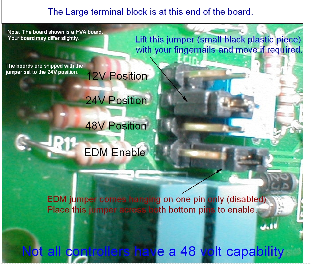
Click to enlarge.
Most of our controllers have a jumper block that allows you to control the controller's sensing voltage. This is basically the voltage of your battery bank, that the controller will be monitoring. The jumper block is comprised of two columns of 4 rows of brass pins (8 pins total. See the diagram above). These rows of pins can be shorted across via a the jumper, which is a small black piece of plastic with a brass liner on the inside. These little jumpers can be lifted with your fingernails and inserted into any one of the rows (across two horizontal brass pins). Please note, regardless of the jumper setting, no up shift or down shift from input to output voltage is done by the controller. This jumper setting simply tells the controller what voltage your battery bank is so it can determine what trip point(s) are applicable.
The image above shows the jumper has been set to the 24 volt position. This means the controller is currently set to operate with a 24 volt battery bank. Move the jumper down one position (lift it out and reinsert it), to use the controller in a 48 volt system. Move this same jumper up to the 1st position to use it in a 12 volt position. (Not all controllers have a 48 volt capability)
As shipped, the EDM jumper is hanging on one pin only. This means that the EDM mode has not been enabled. To enable EDM, lift the bottom jumper up, and insert it into the bottom two brass pins of the jumper block. Please see the manual for more information on the EDM mode.
All of the Coleman Air controllers require a battery bank; they will not work when hooked up directly to a wind turbine or solar panel, and most likely will be damaged very quickly if you attempt to hook up the controller to an energy source, and have not terminated it first to a battery.
What size fuse do I need as a replacement for my C150,C440 or C60 controller.
The C440 and C150 series controllers use a 2 amp, 250 volt fuse. The C60 uses a 1 amp fuse. These are regular speed (not slow blow) and can be obtained at most hardware or auto supply stores.
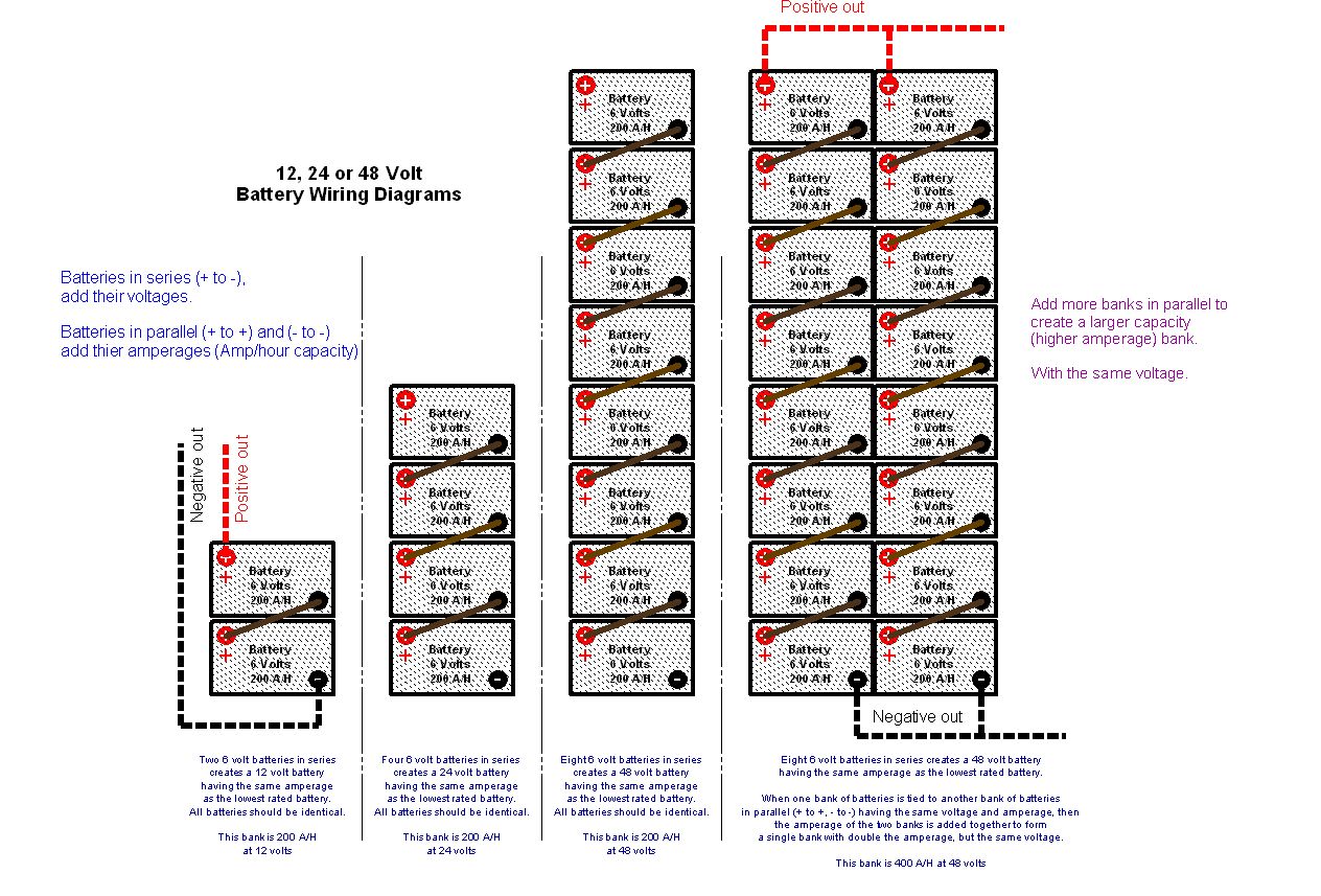
How do I wire my batteries (or solar panels) together to make a 12v, or 24v or 48v battery bank or solar array?
Batteries connected in series (+ to -) sum (add) their voltages. Batteries in parallel (+ to + and - to -) sum their amperages. When you put two 12 volt batteries in series, you get a 24 volt battery bank having the same amperage as the lowest amperage rated battery in the group. Only batteries of equal capacity, age, and voltages should be used in series and/or parallel connections.
This same concept is relevant to solar panels. Panels in series sum their voltages, panels in parallel sum their amperages. Panels of differing voltages can be put in series, but this is rarely required. Panels of differing amperages can be used; however, additional power losses may be experienced.
See the diagram below for examples of wiring 12, 24 or 48 volt battery banks.
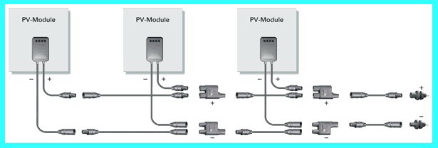
How to Parallel Solar Panels
Do you offer software/firmware updates to your products.
Yes! As part of our on going quality control and research, we are often making improvements and updates to the software running within the microprocessors of our controllers. To allow our customers to take advantage of these updates, we may send out updated processors from time to time. These updates may be as a result of our finding a “bug” or you may simply desire to have the latest version of the software; which, if available for your particular controller, may be purchased for a nominal charge.
If you have received an updated microprocessor for your controller, please see this instruction guide on how to make this replacement.
http://manuals.colemanair.us/shared/HVAD_ProcessorReplacementInstructions.pdf
Other Links
Picaxe to OLED interface example for software engineers
Lightning and Grounding
Getaway Power specializes in tough, USA made, EMP Hardened controllers, meters and accessories.